In the architecture of modern vehicle systems, the instrument cluster is the primary gateway for real-time performance tracking. While a speedometer failure is traditionally associated with a faulty sensor, the technical reality is that the dashboard is highly sensitive to the health of the charging system. For engineers and technicians, the question is vital:
Can a bad alternator cause the speedometer not to work? The answer is 'yes,' primarily due to voltage instability and electromagnetic interference.
1. The Digital Foundation: Stable Voltage and VSS Logic
Modern vehicles utilize a
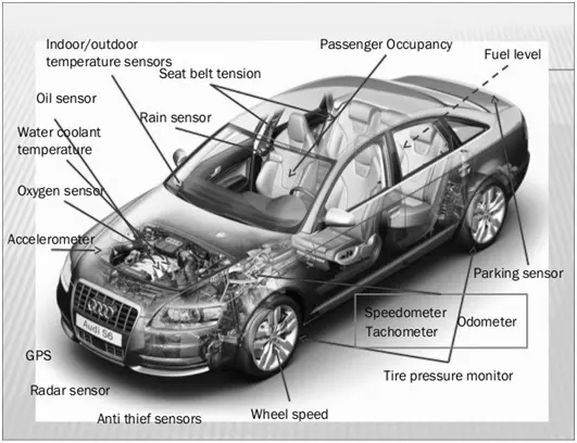
Vehicle Speed Sensor (VSS), typically a Hall Effect or variable reluctance sensor, to track velocity. This sensor generates a frequency-based pulse train that the
Engine Control Module (ECM) translates into a speed scalar.
This entire data chain depends on a 'Single Source of Truth': stable DC voltage. When an alternator fails to provide a consistent 13.5V to 14.7V, the ECM may undergo 'load shedding,' intentionally disabling non-critical telemetry like the speedometer to preserve voltage for ignition and fuel injection systems.
2. The Technical Culprit: AC Ripple and Signal Noise
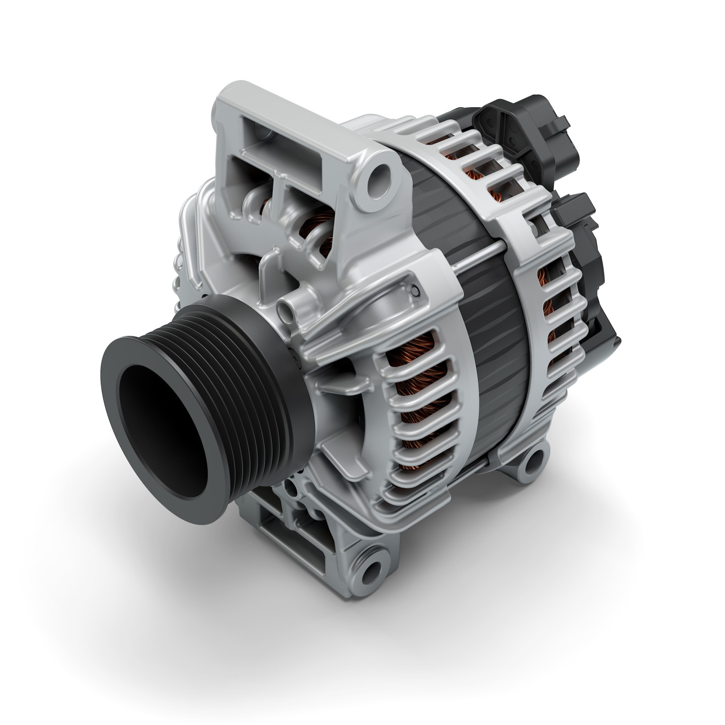
An alternator generates Alternating Current (AC), which is converted to Direct Current (DC) by a diode bridge. When a diode fails, it allows
AC Ripple Current to leak into the vehicle's electrical network.
*
Signal Drowning: The VSS sends a low-amplitude pulse signal. High AC ripple creates electromagnetic noise that effectively 'drowns out' the speed signal.
*
ECU Rejection: The ECM, seeing a corrupted or 'noisy' square wave instead of a clean frequency, will reject the data as unreliable and set the speedometer output to zero to prevent displaying inaccurate information.
3. Diagnostic Workflow: Is it the Sensor or the Charging System?
To isolate the root cause, technicians must look beyond simple mechanical failure and perform a systematic electrical audit:
Step 1: DC Voltage Load Test
With the engine running and high-load accessories (headlights, heater) active, measure the voltage at the battery terminals. A reading below 13.0V indicates the alternator is failing to meet the vehicle's current demands.
Step 2: AC Ripple Detection
Switch the multimeter to the AC setting. A reading higher than
0.5V AC confirms that the internal rectifier diodes have failed, creating the electrical interference responsible for erratic dashboard behavior.
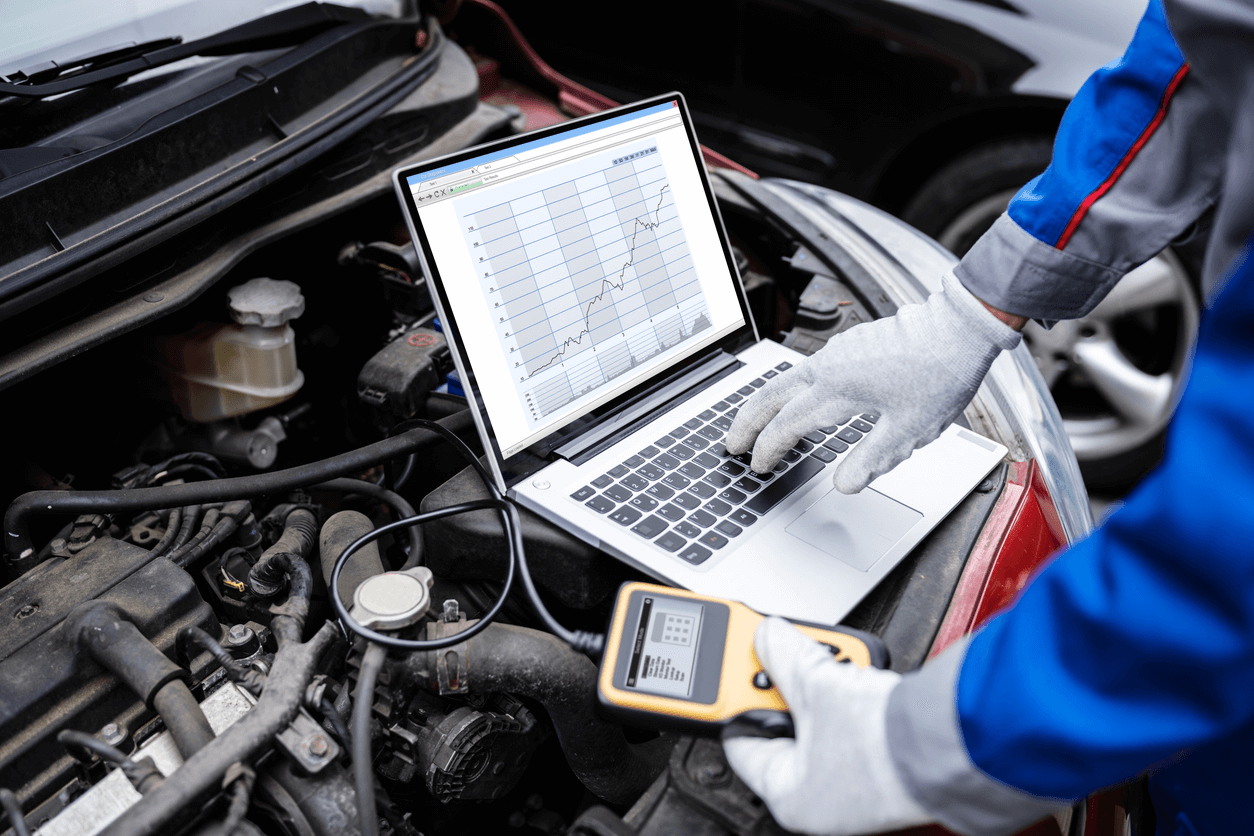
Step 3: OBD-II Telemetry Verification
Using a diagnostic scanner, query the 'Vehicle Speed' PID. If the scanner shows a steady speed while the dashboard remains at zero, the issue is likely a communication fault within the
CAN-bus or the instrument cluster itself. If the scanner also shows zero speed, the fault lies in the VSS signal path or the alternator's interference with the ECM.
4. Impact on Automated Subsystems
A dead speedometer caused by an alternator issue is rarely an isolated problem. Because the transmission controller uses speed data to modulate shift solenoids, electrical interference often results in 'limp mode' or harsh shifting. Furthermore,
Anti-lock Braking Systems (ABS) and
Traction Control rely on the same stable voltage to monitor wheel-speed sensors, leading to a cascade of automated safety system failures.
Conclusion
A car speedometer is not merely a mechanical gauge; it is a digital representation of kinetic data that requires a pristine electrical environment. When an alternator fails, it corrupts the very voltage the system needs to maintain its 'Single Source of Truth.' By utilizing multimeters and oscilloscopes to detect AC ripple, owners can prevent a total telemetry blackout and ensure their vehicle's automation suites remain operational.