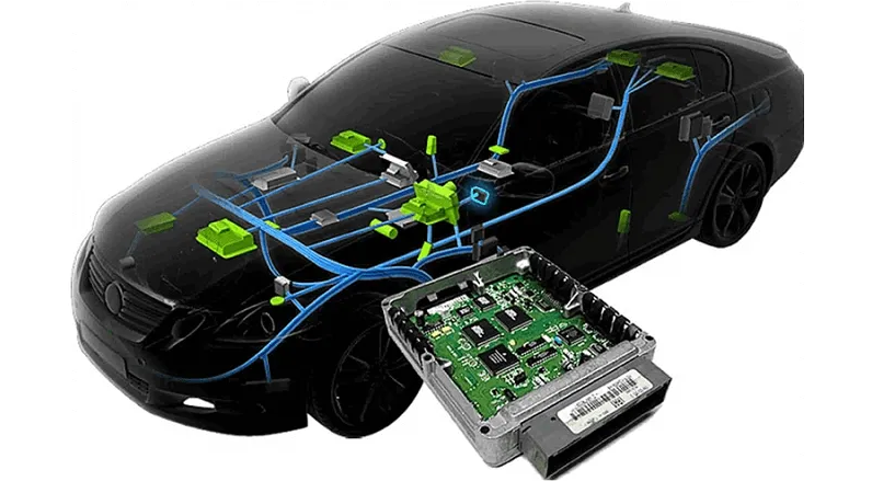
1. The Foundation: The Electrical Return Path
Modern vehicles function as a Local Area Network (LAN) using the metal chassis as a common ground. If a ground strap is compromised by oxidation or loose hardware, the circuit faces high resistance. Instead of a linear data stream, the modules experience 'Floating Grounds,' where the baseline reference voltage shifts, corrupting the data exchanged between the engine and transmission.2. Signal Aliasing: Why the Speedometer Jumps
Most speedometers utilize a Vehicle Speed Sensor (VSS), which is a frequency-based pulse generator. The computer interprets a clean 'square wave' to determine velocity.* Signal Degradation: A poor ground introduces electrical interference (EMI). The computer may detect this noise as extra 'pulses,' causing the speedometer needle to jump erratically, or it may 'drown out' the signal entirely, causing the needle to drop to zero despite vehicle movement. * Reference Shift: Many sensors operate on a regulated 5V reference. A grounding bottleneck can cause this baseline to float. This confuses the digital-to-analog conversion in the instrument cluster, leading to inaccurate telemetry.
3. The Domino Effect: Transmission Automation Failure
The Transmission Control Module (TCM) is a slave to the VSS data. If a bad ground corrupts the speed signal, the TCM's automated shifting logic fails: * Phantom Shifting: If the TCM receives a noisy signal that suggests a sudden drop in speed, it may execute a violent downshift into a lower gear to match the perceived (but false) velocity. * Solenoid Starvation: Shifting is executed by pulse-width modulated (PWM) solenoids. High resistance in a ground path limits the current ($I = V/R$). Without sufficient amperage, solenoids cannot move hydraulic valves effectively, resulting in slipping gears or 'Limp Mode'.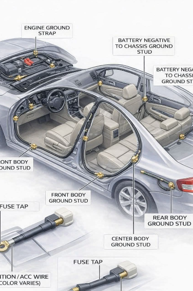
4. Diagnostic Workflow: The Voltage Drop Test
To identify a 'ghost' ground, technicians utilize the Voltage Drop Test, which measures the electricity 'lost' while trying to return to the battery.1. Setup: Set a multimeter to DC Volts (mV scale). Place one probe on the negative battery post and the other on the transmission casing. 2. Load Test: Start the engine and activate high-load accessories (headlights/AC). 3. Evaluation: A reading above 0.1V (100mV) confirms a grounding bottleneck. Electricity is literally 'piling up' because the return path is restricted.
Conclusion
Automotive automation is only as reliable as its electrical environment. If your speedometer is erratic or your shifting is harsh, the solution is often found in the physical connections of the circuit. By maintaining clean, low-resistance ground paths, you ensure that the vehicle's sensors and modules can communicate without the interference of electrical 'ghosts'.