1. The Evolution: From Cables to CAN-bus
Historically, speedometers were driven by a physical cable connected to the transmission. In the digital era, vehicles utilize the Controller Area Network (CAN-bus) to share telemetry. Most vehicles manufactured in the last two decades have transitioned from a dedicated transmission-mounted sensor to using the Wheel Speed Sensors (WSS)—the same hardware that manages your ABS—to calculate road speed.2. The Technical Link: Data Handshaking
Your ABS functions by monitoring the rotational frequency of each wheel via a Hall Effect or variable reluctance sensor. The ABS module processes these pulses to detect wheel lock-up. However, the Engine Control Unit (ECU) also ingests this pulse frequency to determine overall velocity for: * Dashboard Speedometer Display * Transmission Shift Logic * Adaptive Cruise ControlIf the specific sensor used for speed calculation (often a rear-wheel sensor) fails or the ABS module encounters a logic error, the data feed is severed. The ECU effectively 'goes blind,' resulting in a speedometer that drops to zero or displays erratic magnitude.
3. Symptoms of an ABS-Related Blackout
Because these systems are integrated through automation, failure rarely occurs in isolation. Technicians look for the 'Warning Light Trifecta': * The Dead Needle: The speedometer remains at zero despite vehicle movement. * Cascading Warnings: Simultaneous illumination of the ABS, Traction Control (TCS), and Check Engine (CEL) lights. This indicates a system-wide handshake failure on the data bus. * Limp Home Mode: The transmission may stay in a lower gear (e.g., 2nd or 3rd) because it lacks the speed telemetry required to execute shift logic safely.4. Diagnostic Workflow: Automating the Fix
To isolate the root cause, technicians leverage real-time data analysis rather than physical part-swapping:Step 1: OBD-II Telemetry Audit
Using a diagnostic scanner, query the 'C' (Chassis) codes. A code such as C0035 (Front-Left Wheel Speed Sensor Malfunction) identifies the specific node of failure. High-end scanners allow for 'Live Data' monitoring, where you can verify the pulse frequency of each wheel individually.Step 2: Signal Integrity Check
Inspect the sensor's magnetic pick-up and the 'tone ring' (the notched ring on the hub). Debris, metallic 'fuzz,' or a cracked ring will create electrical 'noise' that the ECU cannot translate into a stable speed reading.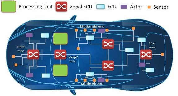
Step 3: Harness Inspection
Since WSS wiring is exposed to extreme vibration and road salt, 'ghost' readings are often caused by frayed insulation or oxidized connectors rather than a faulty sensor.
Conclusion
In the era of Software Defined Vehicles (SDVs), the speedometer is merely a visualization of sensor data generated by the braking system. When your ABS affects your speedometer, it is a reminder that the vehicle is a synchronized digital platform. By utilizing OBD-II waveform analysis and ensuring sensor integrity, you can maintain the 'Single Source of Truth' required for safe and accurate vehicle telemetry.