1. The Digital Handshake: Signal vs. Noise
Modern Speedometers and Transmission Control Modules (TCMs) rely on high-speed digital signals rather than mechanical cables. In a car, the metal chassis acts as the common return path. If a ground strap is compromised by corrosion, electricity faces resistance, creating 'electrical noise' or RFI (Radio Frequency Interference).
2. Can a Bad Ground Cause Speedometer Problems?
Your speedometer relies on the Vehicle Speed Sensor (VSS), which generates a pulse-width frequency. A poor ground causes the 'reference voltage' (the baseline zero) to float, leading to: * The Jumping Needle: If the ground is loose, the ECM sees extra 'pulses' created by electrical interference, causing the needle to bounce wildly. * Signal Dropout: Heat increases electrical resistance. A marginal ground may work during a cold start but fail as the engine reaches operating temperature, causing the speedometer to drop to zero.3. The Shifting Nightmare: Confused TCM Logic
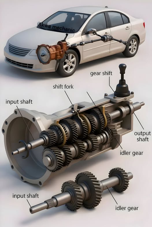
The TCM uses the speed signal to execute automated shifting. If a bad ground garbles this data, the results are often severe: * Erratic Shifting: The TCM may detect a momentary 'zero' speed signal while at velocity, triggering a violent downshift into a lower gear. * Limp Mode: Most modern vehicles enter a 'Limp Home' state if they detect inconsistent electrical telemetry, locking the transmission in a single gear to prevent mechanical damage. * Solenoid Chatter: Grounding bottlenecks limit the current needed to fire electronic solenoids. This causes the solenoids to chatter, leading to 'bang' shifts or slipping gears.4. Step-by-Step: Troubleshooting the Path Home
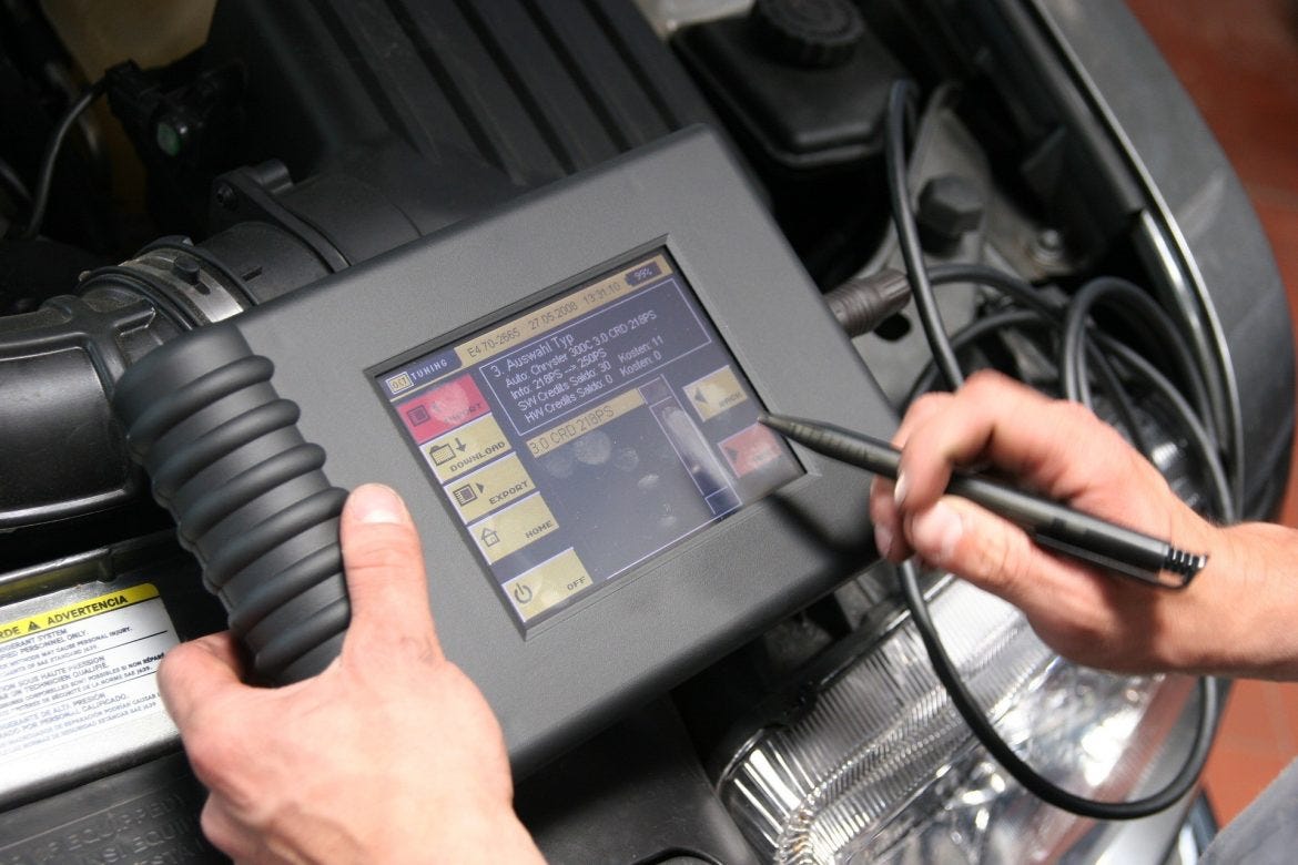
Before replacing expensive hardware, technicians utilize the Voltage Drop Test to identify hidden resistance.1. Visual Audit: Locate the engine-to-chassis ground strap. Look for 'green crusties' (oxidation) or frayed braided wires.
2. Voltage Drop Test: Set a multimeter to DC Millivolts (mV). Place one probe on the negative battery post and the other on the engine block while the engine is running and accessories (lights/AC) are active. * Optimal: A reading < 100mV. * Critical: A reading > 300mV confirms the ground path is restricted, causing electrical 'backflow' into the sensors.
3. Surface Restoration: Scrape mounting surfaces to bare metal, apply dielectric grease to seal the connection, and re-torque all ground bolts.
Conclusion
Automotive automation is only as reliable as its electrical environment. If your speedometer is dancing or your transmission is hunting for gears, the solution is often found in the physical return path of the circuit. By maintaining clean, low-resistance grounds, you banish the 'ghosts' from the machine and ensure accurate vehicle telemetry.