In vehicle instrumentation, the speedometer and odometer represent two distinct interpretations of a single raw data stream. While they appear as independent displays, their functional bond has evolved from a physical, mechanical coupling to a sophisticated software-defined relationship within the Engine Control Unit (ECU).
1. The Mechanical Era: Eddy Currents and Worm Gears
In legacy systems (pre-1990s), the connection was purely physical. A flexible cable geared to the transmission output shaft spun a permanent magnet inside a metal 'speed cup'. This created
eddy currents that generated torque to move the speedometer needle. Simultaneously, the same rotating cable drove a series of
worm gears to mechanically increment the odometer drums. In this architecture, a cable failure resulted in the immediate loss of both velocity and distance telemetry.
2. The Digital Shift: Pulse Train Processing
Modern vehicles utilize a
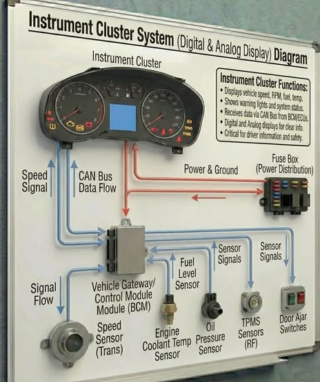
Vehicle Speed Sensor (VSS), typically a Hall-effect sensor that monitors a reluctor ring on the transmission or wheel hub. The VSS generates a square-wave electronic pulse train sent to the ECU via the
CAN Bus (Controller Area Network).
[Image showing the data flow from VSS sensor through the CAN-bus to the dashboard]
The ECU then processes this single 'Source of Truth' through two parallel logic paths:
*
Frequency Analysis (Speed): The ECU calculates the time interval between pulses ($f = 1/T$) to derive instantaneous velocity.
*
Accumulation Logic (Distance): The ECU functions as a digital counter, adding pulses to a non-volatile memory registry. Once a specific pulse threshold (determined by the tire's rolling radius) is met, the odometer increments.
3. Hardware Failures vs. Logic Errors
In the digital age, it is technically possible for the speedometer to fail while the odometer remains functional. This occurs when the
stepper motor driving the physical needle malfunctions, even though the ECU continues to broadcast accurate distance data packets over the CAN bus. Conversely, a digital display glitch might mask the odometer reading while the speedometer continues to process frequency-based velocity.
4. Automation and Calibration Deltas
For developers utilizing OBD-II automation, the VSS pulse-to-distance ratio is the critical variable. Modifications such as aftermarket tire sizes alter the
Rolling Radius, introducing a systematic error in both speed and distance. Advanced telematics systems now automate the correction process by cross-referencing VSS data with GNSS (GPS) ground truth, allowing the ECU to self-calibrate and maintain precision across varying mechanical conditions.
Conclusion
Are the speedometer and odometer connected? Yes—they are now 'data-coupled'. They represent a shared pulse stream filtered through different algorithms to provide a complete picture of vehicle telemetry. Understanding this electronic heartbeat is essential for anyone maintaining or automating modern automotive systems.