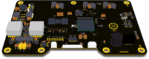
1. The Electrical Loop: How Your Speedometer Works
Modern vehicles utilize a Vehicle Speed Sensor (VSS), typically a Hall Effect or variable reluctance sensor, to track velocity. This sensor generates a frequency-based pulse train that the Engine Control Module (ECM) translates into a speed scalar.For this communication to maintain integrity, the circuit requires a 'Single Source of Truth'—a clean ground. In a DC system, the vehicle's chassis acts as the return path to the battery. If this path is compromised by corrosion or loose hardware, the electrical 'data packets' (the speed pulses) become distorted or fail to reach the threshold required for the ECM to register a reading.
2. Why a Bad Ground is a Signal Killer
Grounding issues manifest in two primary ways within a digital dashboard system: * Electrical Noise: When a ground connection is weak, current seeks alternative paths through other sensors. This creates electromagnetic interference (EMI) that drowns out the low-voltage pulses from the VSS. The ECM sees 'gibberish' instead of a clean square wave and defaults the speedometer to zero to avoid displaying false magnitude.* Voltage Drop: According to Ohm’s Law ($V = I \times R$), as resistance ($R$) increases due to a bad ground, the available voltage ($V$) at the sensor drops. If the VSS or the instrument cluster receives less than its operational threshold (typically 5V or 12V depending on the system), the component will fail to trigger or enter a 'brownout' state.
3. Diagnostic Workflow: Hunting the 'Ghost'
To isolate a grounding fault, technicians must look beyond the sensor itself and perform a systematic electrical audit:Step 1: Visual and Physical Audit
Inspect the main grounding straps—the braided cables connecting the engine block to the chassis and the negative battery terminal to the frame. In regions where road salt is prevalent, oxidation (white or green crust) creates a high-resistance barrier.
Step 2: The Voltage Drop Test
This is the professional standard for identifying hidden resistance. Set a digital multimeter to the millivolt (mV) setting. With the engine running and under load (lights and fan on), place one probe on the negative battery terminal and the other on a clean spot on the engine block. * Optimal: A reading < 100mV. * Critical: A reading > 300mV indicates a significant grounding failure that is likely disrupting sensor telemetry.Step 3: VSS Continuity Check
Unplug the VSS harness and measure the resistance between the ground pin and the vehicle frame. A reading higher than 5 Ohms suggests a break or high-resistance point in the wiring harness itself.4. Precision Mitigation
Once the fault is identified, the repair must be deterministic to prevent recurrence: 1. Surface Restoration: Scrape the mounting surface to bare, shiny metal to ensure a low-resistance interface. 2. Chemical Protection: Apply dielectric grease after the connection is made to seal the joint from moisture and oxygen, preventing future oxidation. 3. Mechanical Integrity: Use star-style lock washers; their teeth penetrate the metal surfaces to maintain a constant connection under engine vibration.