1. The Physical Interface: Casing Terminations
Universality is primarily restricted by the 'Port' architecture at the instrument cluster and transmission. Over decades, two dominant standards emerged: * Screw-on Connectors: Utilizing a threaded nut (common in pre-1980s GM/Ford models). * Snap-on (Press-fit) Connectors: Utilizing a plastic locking clip (standardized in the 1980s-90s). These interfaces are physically incompatible without specialized adapters, similar to the delta between USB-A and USB-C hardware.
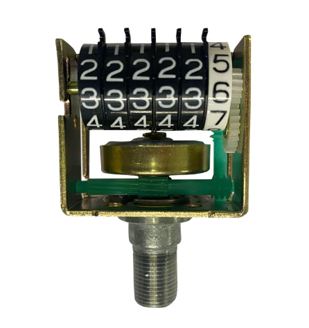
2. Inner Core Geometry and Drive Ratios
The 'data carrier' is the wound-wire inner core. Its effectiveness depends on the Tip Geometry. The drive ends are typically square, flat (tang-style), or splined. Even a 0.020-inch variance in square-drive width (e.g., 0.104" vs 0.124") will cause engagement failure or catastrophic stripping of the speedometer's plastic internal gears. Furthermore, if the cable length is not calibrated to the specific housing, excess slack leads to 'needle bounce'—the mechanical equivalent of high signal jitter.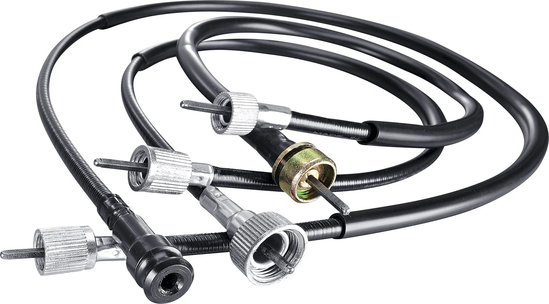
3. The 'Universal Kit' as a Framework
'Universal Speedometer Cable Kits' are best viewed as a development framework rather than a finished product. They provide a raw inner core and housing that must be compiled to specific measurements.To ensure accurate velocity reporting, the user must manually crimp the transmission-side tip and cut the casing to match the OEM routing. For those seeking to bypass these mechanical limitations, the gold standard is the GPS Signal Generator—a device that threads onto the transmission to convert rotational torque into a digital pulse, allowing for an automated transition from analog hardware to high-fidelity digital telemetry.