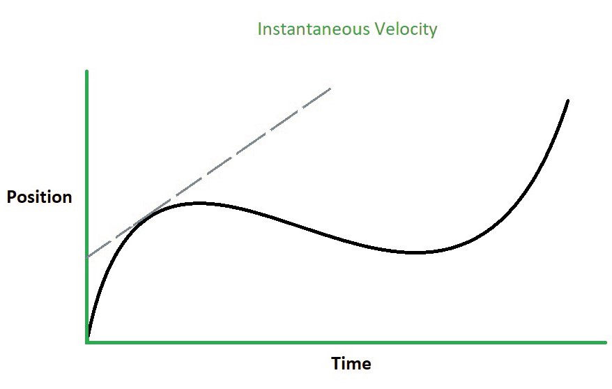
1. The Core Definition: Instantaneous vs. Average Speed
In the realm of physics and telemetry, we must distinguish between two types of velocity measurements: * Average Speed: A retrospective calculation of total distance divided by total time. It provides a historical narrative but no real-time situational awareness. * Instantaneous Speed: The speed of an object at a specific moment in time ($t$).In calculus terms, it is the derivative of your position with respect to time ($v = ds/dt$). For automotive automation, this is the most critical data point because it allows onboard computers to make split-second decisions regarding safety and performance.
2. How the Data is Captured: The Evolution of Speed Sensing
The technology has shifted from purely mechanical induction to high-frequency electronic pulses.Mechanical Era: Eddy Currents
Historically, a flexible cable connected the transmission to the speedometer. Inside the cluster, this cable spun a magnet inside a metal 'speed cup'.As the magnet rotated, it induced tiny electrical currents (eddy currents) in the cup, creating magnetic torque that pulled the needle against a hairspring. This was an elegant, analog form of automation—converting rotational energy directly into visual data.
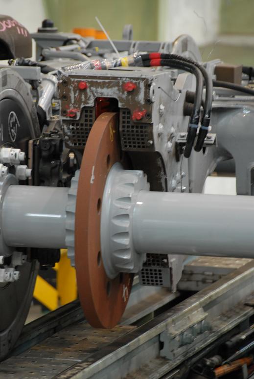
Digital Revolution: Hall Effect Sensors
Modern vehicles utilize electronic Vehicle Speed Sensors (VSS), typically Hall Effect sensors located on the transmission or wheel hubs.As the wheel spins, the sensor generates a series of digital pulses. The Engine Control Unit (ECU) counts these pulses per second and calculates the speed based on the programmed circumference of the tires. This data is then broadcast across the CAN bus to the instrument cluster.
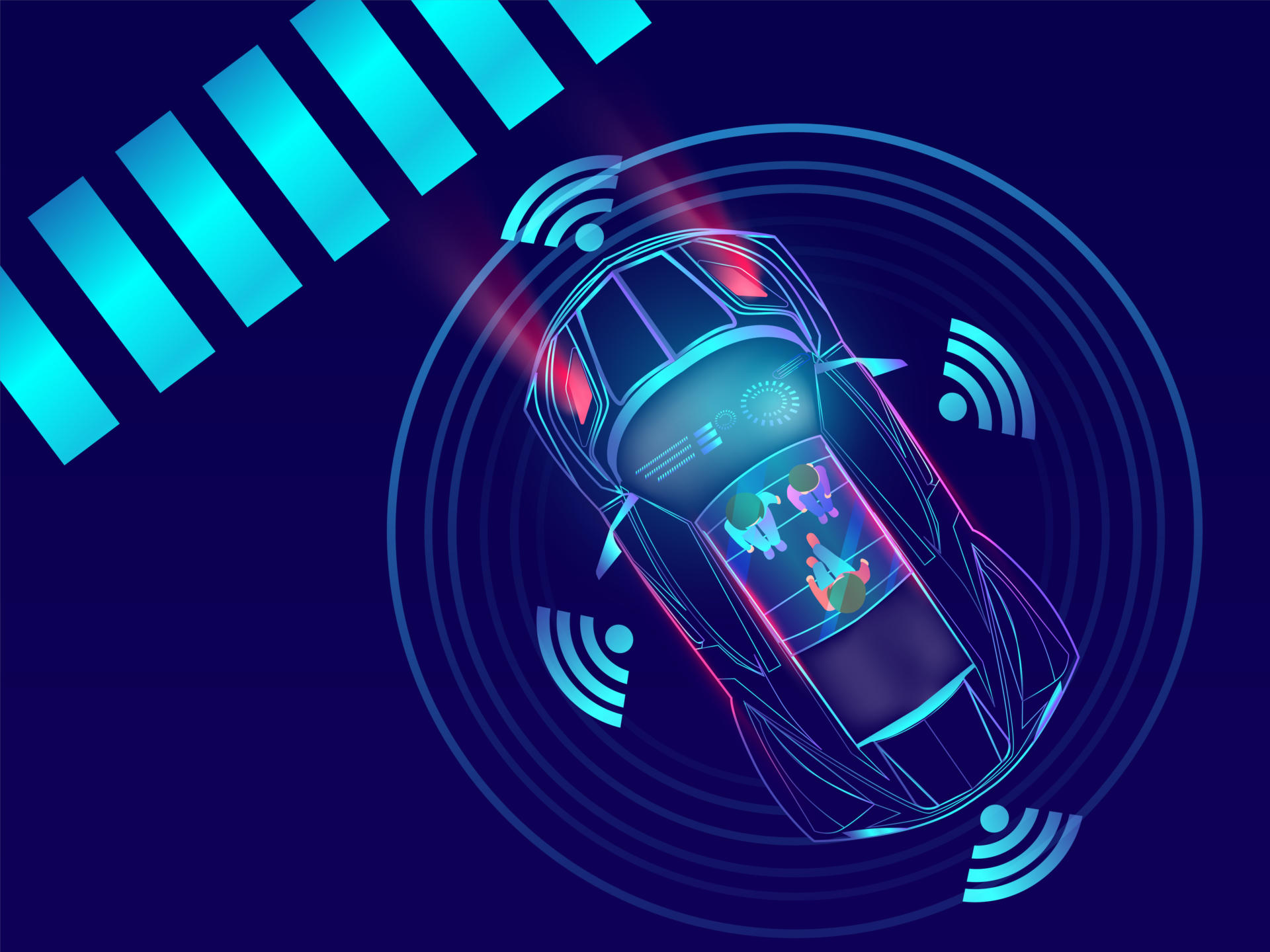
3. The Automation Angle: ADAS and Telematics
In the modern ecosystem, speed data is a primary input for automated control loops:* Adaptive Cruise Control (ACC): ACC uses instantaneous speed data in conjunction with Radar or LiDAR. The system creates a feedback loop; if the vehicle ahead decelerates, the ECU automatically adjusts the throttle or applies brakes to maintain a safe gap. * Fleet Management Telematics: Speed is logged and transmitted to the cloud via OBD-II interfaces. Automated systems track instantaneous peaks to provide safety scores and real-time alerts for operational efficiency.
4. Variables Affecting Speedometer Accuracy
Because the speedometer infers speed from rotation, physical variables can compromise the 'Ground Truth': * Tire Wear: As tread wears down, the tire circumference shrinks, meaning it completes more rotations to cover the same distance. This causes the speedometer to read higher than actual speed. * Manufacturer Calibration: To comply with safety standards (e.g., ECE R39), many manufacturers calibrate speedometers to be slightly 'optimistic' (showing 1-2 mph faster than reality).