1. The Digital Evolution: Why Voltage is the 'Single Source of Truth'
Unlike legacy mechanical speedometers driven by physical cables, modern units are electronic displays that rely on the Vehicle Speed Sensor (VSS).
The VSS sends a frequency-based pulse signal to the Engine Control Unit (ECU). These microprocessors require a stable, 'clean' DC signal (typically 12.6V). When a battery undergoes internal sulfation or a cell failure, it loses its ability to act as a capacitor, failing to filter the electrical 'noise' generated by the alternator. This noise corrupts the pulse data, causing the speedometer to display erratic values or drop to zero.
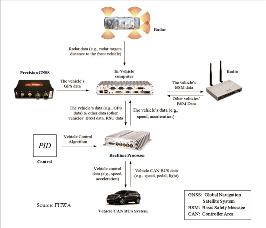
2. The CAN Bus Connection: Data Traffic Jams
Modern vehicles utilize the CAN Bus (Controller Area Network) protocol to share data between modules.When battery voltage drops below a specific threshold (often 10.5V during load), the communication modules can undergo a 'brownout.' In this state, the Instrument Cluster loses its data handshake with the ECU. Because the 'Speed' message is lost in the network noise, the needle defaults to zero as a safety protocol to avoid displaying false magnitude.
3. Diagnostic Workflow: Is it the Sensor or the Battery?
Before replacing expensive sensors, technicians should perform a systematic electrical audit:Step 1: Static and Load Voltage Test
A healthy battery must maintain 12.4V–12.6V at rest. During the 'cranking' phase, if the voltage drops below 10V, the internal plates are likely compromised, causing the ECU to 'reboot' and lose speedometer telemetry temporarily or permanently.Step 2: Grounding Integrity Check
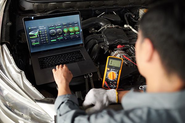
Automotive electronics rely on a low-resistance path to the chassis. Corrosion on the negative battery terminal or the engine ground strap creates a 'bottleneck,' resulting in fluctuating voltage that mimics a faulty speed sensor.Step 3: OBD-II Communication Audit
Using a diagnostic scanner, look for 'U-prefix' codes (e.g., U0121 - Lost Communication with ABS). Since many speedometers pull data from ABS wheel-speed sensors, a battery-induced communication failure in the ABS module will immediately paralyze the speedometer.4. Mitigation: The Role of AGM Technology
For tech-heavy vehicles, Absorbent Glass Mat (AGM) batteries are recommended. They provide a more stable voltage floor and better resistance to the vibration-induced plate damage that causes erratic sensor readings.